
Applications
- Electron microscopy - SEM, in both SE and BSE mode, SEM/FIB and TEM (with special version)
- Scanning Microscopies and Profilometry - STM, AFM, the pattern height is 70nm
- Optical Microscopy - transmitted, reflected, bright/dark field, differential contrast and confocal
- Chemical mapping - EDS, WDS, XRF, XPS, Auger and others. The pattern is fabricated using 30nm CrO2 over 40nm Cr on quartz
- Particle Size Counting - series of circles, squares & rectangles for calibration confirmation
Pattern Design
The fifth generation MRS-4.2 is fabricated using the high accuracy direct write electron beam manufacturing equipment. The pattern is anti-reflective chromium (30nm Cr2O over 40nm Cr) on quartz. Imaging in both secondary and back scattered mode is very high. The pattern is coated with a proprietary conductive material which allows for SEM imaging at any accelerating voltage.
Geometric design
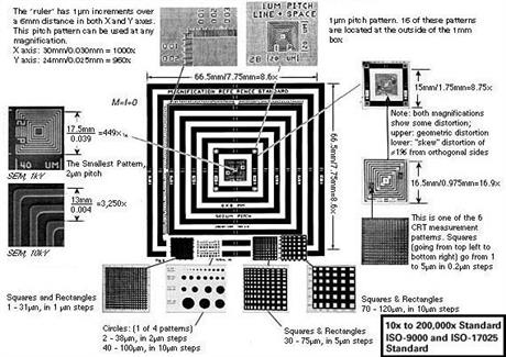
The MRS-4 has groups of nested squares with pitches of 1/2µm, 1µm, 2µm, 50µm and 500µm. The largest pattern has an overall dimension of 8mm square with lines and spaces of 250µm. This can be used to check magnifications between 10 - 100x. The 50µm pitch patterns are useful from 100 - 1000x magnifications. The 2, 1 and 1/2µm pitch patterns allow calibrations up to 200,000x. Incorporated into the standard are X & Y rulers with 6mm length with 1µm increments.
Dimensions/Retainers
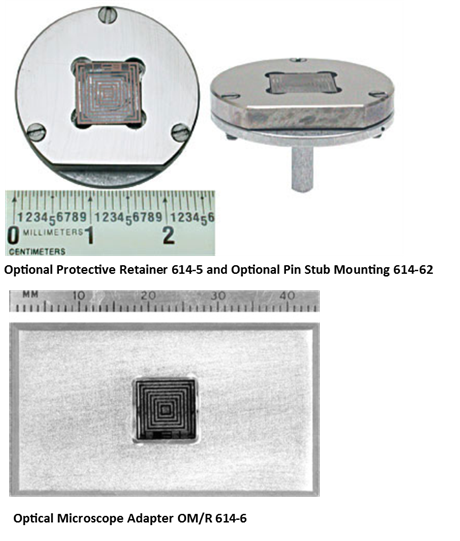
The overall size of the MRS-4 is approx. 9 x 9 x 2.3mm. Since the standard is made on quartz, it easily chips. We highly recommend ordering the optional protective retainers for the MRS-4.
Selected MRS-4 Patterns and Details of Traceability
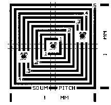
50µm pitch pattern. The overall width is 1mm. Measure magnification using multiple pitches totaling 0.950mm, as above.
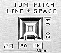
1µm pitch pattern. 16 of these patterns are located at the outside of the 1mm box.
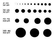
Circle pattern from 2 to 100µm. 4 sets are included.
SEM Magnification Calibration and Stage Micrometer MRS-4
Details of Traceability to NIST, NPL or ISO 9000 Compliance
Magnification Calculations
The fundamental magnification (M) calculation involves dividing a chosen image (I) dimension by its corresponding object (O) dimension, where M = I/O
The standard must be perpendicular to the exciting beam to prevent image foreshortening. If an SEM image containing 5 cycles of the 2µm pitch pattern (10µm) is represented over a 90mm distance on the SEM CRT, by a vernier, or on film, the magnification would be (90/0.01) 9,000X. If the indicated magnification were 10,000X, the error would be –10%.
Linearity Measurements
Imaging distortion is characteristic of all types of imaging systems. It appears as a barreling, pincushion and skew, and is generally measured as a percentage deviation from linearity (using the straight edge of the MRS-3 or MRS-4, a 1% distortion would be a 1mm deviation in the straightness of a 100mm line).
Tilt Angle Determination
For SEM’s, the MRS-3/MRS-4 should be normal to the electron beam (0º tilt). Both the X and Y magnifications should be equal. If the specimen is then tilted about the X-axis the magnification will decrease along the Y-axis (due to foreshortening) by the cosine of the tilt angle. For example, if the (100µm)2 boxes measure 100µm in the X-axis and 50µm in the Y-axis, the tilt angle would be:
Tilt angle = cos-1 (50/100) = 60º
Traceability
A CRM (certified reference material) guarantees dimensions. Most commercially available standards have unknown precision. Grids and spheres may change size under vacuum or are distorted. MRS-4 and MRS-3 are offered with or without traceability. The non-traceable standard differs only in documentation and cost. Traceability in the X and Y dimensions is established from "masters" that have been measured by NPL (National Physics Laboratory), the NIST counterpart in the U.K. The "Z" dimension (100nm) has been established on MRS "masters" by NIST.
Recertification Program
Annual recertification is required. This practice is common with devices such as gage blocks and electronic instruments. Over years, it has been found that several standards could not be recertified due to physical damage and excessive contamination. Physical damage is most often caused by optical microscope objectives being drawn across the pattern surface, or abuse. It is possible that electron beam damage and corrosion from storage in a hostile environment will require service and recertification, which will insure that your standard will perform its proper task. Consult your Quality Department for advice. They are most familiar with the company’s quality requirements as it relates to ISO-9000, QS9000 or ISO-Guide 25 or 17025.
Operating Parameters
Optical microscopes can use the MRS-4 in all imaging modes. The anti-reflective coating greatly reduces scattered light enabling high contrast images to be observed and photographed. Magnifications can be measured directly by viewing CRTs, in reticles mounted within the ocular, or directly on photomicrographs. For instruments with verniers or electronic calipers, distance measurements can be verified using a pitch pattern of appropriate size. If the application primarily consists of optical microscopy, we suggest ordering the MRS-4 without the conductive coating since it reduces the reflected optical contrast in the image.
ASTM E766-98: Standard practice for calibrating the magnification of a Scanning Electron Microscope
The American Society for Testing and Materials has published this standard. The copyrighted text is available from ASTM. A convenient way of obtaining E766-98 (or a later version) is online from the ASTM web site at http://astm.org. This excellent standard offers terms, definitions and guidance to calibrate your instrument’s magnification. Using the standard, you would be able to calibrate to better than 5% precision in the magnification range from 10X to 50,000X. With the one-half micrometer, "1/2µm" pitch, it is reasonable to extend the range to 200,000 using the MRS-4 since there was no such standard when it was updated in 1998.
E1951-98 Standard Guide for Calibrating Reticles and Light Microscope Magnifications
This guide covers methods for calculating and calibrating light microscope magnifications, photographic magnifications, video monitor magnifications, grain size comparison reticles, and other measuring reticles. Reflected light microscopes are used to characterize material microstructures. Many materials engineering decisions may be based on qualitative and quantitative analyses of a microstructure. It is essential that microscope magnifications and reticle dimensions be accurate.
The calibration using these methods is only as precise as the measuring devices used. It is recommended that the stage micrometer or scale used in the calibration should be traceable to the National Institute of Standards and Technology (NIST) or a similar organization.
Measurements are made by a special SEM where each individual pattern is measured. Other CRM’s may calibrate using optical diffraction. This technique averages over large patterned areas, it does not measure individual "pitches" – like your microscope.
Test Method: (in compliance with ISO/IEC-17025)
All measurements are performed in vacuum with a modified scanning electron microprobe. The 500µm, 50µm, 2µm pitch measurements are made between the horizontal and vertical tracks through the center of the device. For the MRS-4 the 1µm and ½µm pitch measurements are made through the center of the northwest patterns. For the 500μm through 1μm pitch patterns the measurements start at the inside edge of the left most bar (left column) and the left side of the first bar to the right of center (right column) of the center pattern. The vertical measurements are made the same way starting at the top pattern. For the ½μm pattern twenty measurements are made on the left side and top side of center, starting with the inside of the first bar. Measurements are made through direct comparison with a MRS that has been calibrated against a similar device measured by the National Physical Laboratory (NIST counterpart in the U.K.) thereby establishing an unbroken link of traceability. Each measurement is reported as a "pitch" value, which is the sum of an adjacent bar and space (edge-to-edge) on the pattern. Optional Z-axis measurements (step height) are provided by referencing the measured value against a NIST measured MRS using a Dektak 3030 stylus profilometer. The X & Y data was measured in vacuum while Z measurements are performed in air. For usage: 25°C ±10°C, humidity <90%. Expanded uncertainties are reported with a coverage factor of k=2.